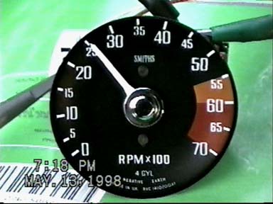
A Better Tach Circuit

Here’s more information about adjusting the MGB Tach to work with a V8 or a V6.
This is looking at the back of the tach. After you remove the front bezel by rotating it till the tabs clear the body. Turn the tack over (carefully – don’t bend the needle) and remove the screws highlighted in green – leave the red one alone.
Here’s a view of the potentiometer I used – tit was a 100k but – i’ve now measured the resistance it’s set to – it’s 46.3K.So you could use a 47k resistor and not bother with the potentiometer. And as you can see you don’t even have to solder real great ð
As long as I had it out again I did some more measuring. The resistance between pins 4 and 7 without my added pot was 47.4K With my pot added it was 23.4 – which is wht you would expect with two 47K resistors in paralell. Keep in mind the tolerance of the resistors -it’s not that exact.
So thinking about this I get – 47k without the added pot gives me a tach for a 4 cylinder engine, adding a 47k resistance gives me a tach for an 8 cylinder engine. You could figure out the resistance needed for a 6 cylinder engine. You being the key word…
In response to an item I posted on the MGB bbs the discussion brought forth another way to make the 4 cylinder tach work for the V8 engines. Larry from Denver relayed an article about putting a potentiometer (pot) across the chip in the 4cyl tach that would make it work on 8 cyl. I tried it out tonight and am posting the results. I took some shots with my video and grabbed stills from it. It’s a pretty painless procedure and could be done easily if you have some soldering experience or know someone that would help out with it. The only part you need is a 100K 10 turn pot. I had one in my junk box, but they’re available from Radio Shack, I wouldn’t think that they are over a couple bucks.
The pot gets soldered on pin 4 and pin 7 of the only chip in the tach. There’s a mark (usually an indentation in the chip case) on the corner of the chip that is pin 1. If you hold that so it’s in the upper left corner, the pins are numbered 1-8 counter clockwise. Here are pictures of where the pot goes and what the pattern looks like for calibrating it. Check out the page “A few Pics & The Spark” for a picture of what the point side of the coil looks like.
Click on the pictures below for larger images.Â
Here’s a pic of the pot soldered to pin 7:

After putting the pot on, I hooked up the scope and calibrated it at 1250 rpm. At 1250 rpm the points are firing at 12ms intervals:

A 4 cycle engine fires once every other revolution, so at 12ms interval it’s .012*4 = 0.048ms/revolution. 60 seconds divided by 0.048 is
To check, I increased the speed to 6ms:

Here’s a diagram I took from British MG V8 but doctored it a bit to show the corrected pin connections. The ovals around the chip make more sense when you look at the physical circuit – they are there to help you see the placement – they are capacitors.
And from another direction, how I soldered it to pin 4:
A 4 cycle engine fires once every other revolution, so at 12ms interval it’s .012*4 = 0.048ms/revolution. 60 seconds divided by 0.048 is
1250 RPM. I set the pot for this:

Using the formula above – (0.006*4) = 0.024. 60Sec/0.024 = 2500 RPM:

Here’s a picture of what I taped when I forgot to turn the camera off:

Designed and Hosted by Zaks.com


